Restraints
The default restraint condition is of “fork ends” at each end of the beam, which is laterally fixed, warping free and the restraints are located at the shear centre. All of these defaults may be changed and additional restraints may be specified. Normally, restraints might be discreet ‘point’ restraints, but the user can select a length of continuous restraint if required. Restraints may be specified at any point with respect to the top of the section, bottom or shear centre. Note that the entered value for the vertical offset of a restraint from the chosen reference must be positive if it is below the reference, and negative if it is above the reference.
Each defined restraint has four stiffness values to restrain the beam against the four components of buckling. The possible input values for any buckling component are as follows:
· Free: This is the default, and it is set by entering ‘0’ in the stiffness input field.
· Fixed (infinitely rigid): This is set by entering ‘F’ or ‘f’ in the stiffness input field.
· Spring (elastic): This is set by entering a numerical value, which represents the stiffness of the spring, in the stiffness input field.
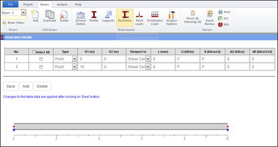
The changes made to the restraints data are applied and the graphics are refreshed when the user clicks on the Save button.